
Chilled Water Plant Design: Why Your Plant Runs Extra Chillers

founder and CEO of Cold Energy (NCT)
The chilled water plant scheme is chosen before the chillers are selected: it decides how many machines run and how much electricity the pumps draw. If water comes back to the plant at a 3 K delta-T instead of the design 5 K, flow rises 1.67 times, pump power up to 4.6 times, and the chillers run at 40–50 % load.
The same pair of chillers either runs steadily or cycles, holds 7 °C or delivers 9 °C, depending on how the pumps, the bypass and the load valves are connected. The chiller does not choose the scheme, but it pays for it. This article is for plant directors and chief engineers with a chiller plant of two or more machines. I covered how the machine itself works in What is a chiller and how does it work, and the mistakes made when choosing one in the 13 most expensive mistakes.
What is a chilled water scheme and why is it chosen before the chiller?
A chilled water scheme is the way chillers, pumps and loads are connected: how many loops, where the pumps sit, which valves are used and how the plant decides how many machines to run. It comes first because it sets the flow through each machine, the number of pumps and the whole control logic.
Start with three questions about the site:
-
How are the loads controlled? With three-way valves (constant flow) or two-way valves (flow varies with load).
-
How many machines, and are they identical? One, several identical ones, or machines of different capacity.
-
How much can flow through a machine vary? This is in the datasheet: minimum and maximum flow and the allowed rate of change. Some machines tolerate a 30 % flow change per minute, others only 2 %.
Flow is calculated as G = Q / (1.163 · ΔT), where Q is cooling capacity in kW and ΔT is the temperature difference in K. For a 500 kW machine on a 7/12 °C schedule that is 86 m³/h; for 1,000 kW it is 172 m³/h.
What chilled water schemes with chillers are there?
There are four working families of schemes: constant flow in a single loop, primary-secondary, variable primary flow, and decoupling through a heat exchanger. Separately you decide whether machines go in parallel or in series: in series when the delta-T is above 9 K and flow is small.
| Criterion | Constant flow | Primary-secondary | Variable primary | Heat exchanger decoupling |
|---|---|---|---|---|
| Valves at the loads | Three-way | Two-way | Two-way | Any |
| Number of machines | 1, sometimes 2 identical | 2 or more, including different sizes | 2 or more, with a wide flow window | Any |
| Control complexity | Low | Medium | High | Medium |
| Pump energy | High at part load | Medium | Low | Higher: a second pump |
| Low delta-T risk | High | Medium | Medium | Medium |
| When to choose | Small plants, constant load | 2–5 machines, comfort and process cooling | Identical machines, time for commissioning | Different fluids, dirty or food-grade water, high static pressure |
On plants with 2–5 machines many designers deliberately choose primary-secondary: it tolerates mismatched machines and does not need long commissioning. Any other scheme the designer should justify with numbers in the design report.
The simplest constant-flow scheme has two traps. The first is three-way valves: at 30 % load the return comes back at about 8.5 °C instead of 12 °C. The second is two chillers on one common pump without isolation valves: water flows through the stopped machine too, and with a 12.2 °C return and 6.7 °C leaving the running machine, the loads get a 9.45 °C mix. The fix belongs in the design stage: each machine gets its own pump or a motorized isolation valve.
How does a primary-secondary loop work and why does it need a bypass?
A primary-secondary loop separates producing cooling from distributing it. The machines run on their own constant-flow pumps; the loads run on their own pumps with variable frequency drives and two-way valves. The bypass (decoupler) takes the difference in flow.
The bypass rules from international practice that we put in our design guide:
-
design flow is 110–115 % of the flow of the largest machine;
-
length is at least 5–10 pipe diameters, so supply and return do not mix;
-
no check valve and no shut-off valves in the bypass: a check valve puts the primary and secondary pumps in series and pushes more than design flow through the machines;
-
the bypass has a flow meter or a pair of temperature sensors.
For a 1,000 kW machine on 7/12 °C this is a bypass for 198 m³/h: a DN200 pipe 1.5–2 m long.
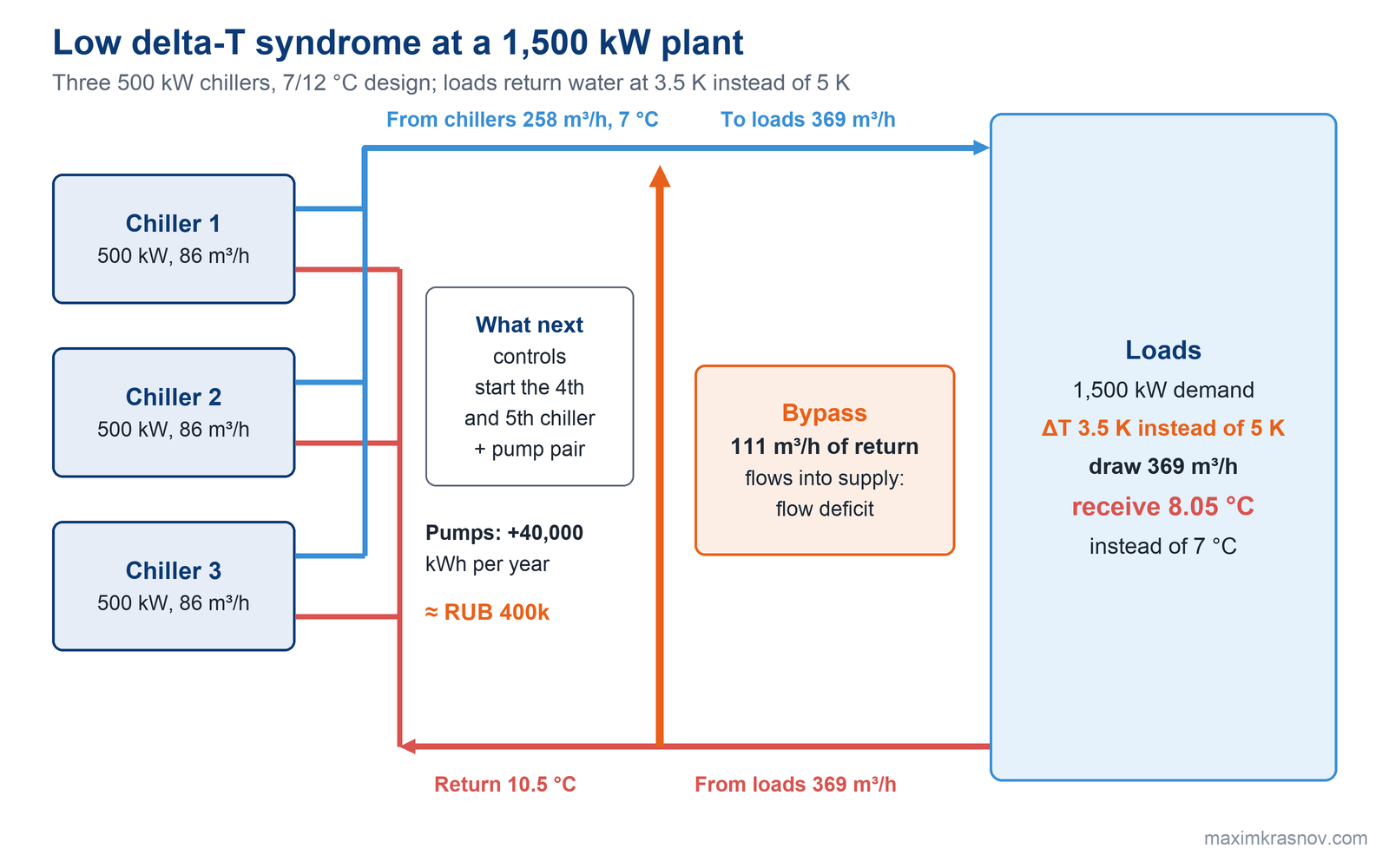
The flow direction in the bypass is the main signal for the controls. Flow from supply to return means more machines are running than needed. Flow from return to supply is a deficit: warm return water is mixed into the supply to the loads, and it is time to start the next machine-and-pump pair.
What is low delta-T syndrome and what does it cost?
Low delta-T syndrome is when water returns to the plant colder than designed. The machines cannot load up, the controls start extra machines to supply the flow, and the pumps move more water than needed. A site designed for 12/7 °C actually runs at 10/7 °C, and for the same capacity flow rises 1.67 times, while pump power by the affinity laws rises 1.67³ = 4.6 times.
Example: three 500 kW machines, 1,500 kW load, design delta-T 5 K, actual 3.5 K.
1. Required flow: 1,500 / (1.163 · 5) = 258 m³/h, exactly three machines.
2. Actual load flow: 1,500 / (1.163 · 3.5) = 369 m³/h.
3. Through the bypass, 369 − 258 = 111 m³/h of return water at 10.5 °C is mixed into the supply.
4. The loads receive (258 · 7 + 111 · 10.5) / 369 = 8.05 °C instead of 7 °C.
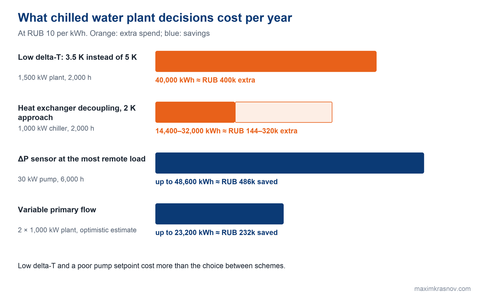
To get back to 7 °C, the plant needs one or two more machine-and-pump pairs while three machines are underloaded. If the secondary pumps run at 30 kW instead of 15 kW because of the syndrome, and the extra pair adds 5 kW, over 2,000 hours that is 40,000 kWh per year on the pumps alone, about RUB 400,000 at RUB 10 per kWh. The syndrome feeds itself: with 8 °C supply the valves open wider and the delta-T drops further.
How do you find the cause of low delta-T on an operating plant?
The cause of low delta-T is found in the plant's temperature and flow history over two or three days. A delta-T drop at part load points to valves and bypasses; a drop in the mornings points to fouled heat exchangers.
Check the causes in order: three-way valves, open bypasses, dirty heat exchangers, oversized valves, loads designed for a smaller delta-T than the plant. Treat the cause: remove three-way valves, install pressure-independent control valves, clean strainers and heat exchangers, start the next machine only once the previous one is fully loaded. A check valve in the bypass does not remove the cause.
If there is no history, the numbers are measured on site: our survey engineer with clamp-on flow meters and temperature and pressure sensors captures the real picture of the site in a day or two. The solution a client came up with on their own almost always turned out more expensive than what we arrived at after measurements.
When does variable flow through the chillers pay off?
Variable primary flow pays off when the machines are identical, have a wide flow window in the datasheet, and there is time for design and commissioning. One group of pumps with variable frequency drives serves both the machines and the loads.
A rough estimate for a 2 × 1,000 kW plant: two 10 kW primary pumps, load at 75 % for half of 4,000 hours. During those hours a primary-secondary loop draws 20 kW; variable flow draws about 0.75³ = 42 %, that is 8.4 kW. The saving is 23,200 kWh per year, about RUB 232,000.
This figure is on the high side: pumps in a variable scheme are larger. And the weak point of the scheme is the transition: when the second machine's valve opens, flow through the first can fall below the datasheet minimum, and both trip on flow. That is why each machine needs an isolation valve, a minimum-flow bypass, a flow meter, and slow valves with a 30–60 second stroke.
When do you need heat exchanger decoupling and what does it cost?
Decoupling through an intermediate heat exchanger is needed when the loops cannot be connected directly: glycol at an outdoor machine and water at the loads, dirty or food-grade process water, an unsuitable temperature schedule, high static pressure in the building. The price of decoupling is the approach: to give the loads 7 °C, the machine has to produce colder water.
According to manufacturers, lowering chilled water temperature by one degree increases compressor power by 1.8–4.0 %. A 1,000 kW machine with 200 kW of compressors and a heat exchanger that needs supply 2 K colder uses 3.6–8.0 % more, or 7.2–16 kW. Over 2,000 hours that is 14,400–32,000 kWh per year, or RUB 144,000–320,000. So decoupling is used only when there is no way around it, with an approach of no more than 2 K.
On the other hand, decoupling opens the door to free cooling. At a powder metallurgy plant we installed a 4.6 MW cooling system with +7/+12 °C water: a Thermax absorption chiller, three NCT cooling towers and an NCT pump station. In summer the towers reject heat from the machine; in the cold season two towers cool the water from +12 to +7 °C and send it through heat exchangers straight to production, with no chiller in the chain. More in Chiller free cooling.
How should pumps be backed up so one failure does not cut cooling?
Pump redundancy is designed so that the failure of any single pump does not stop cooling. Small and medium loops are fine with 1 + 1: a duty and a standby pump, each for full flow. Large variable-flow loops get 2 + 1; the primary loop of several machines gets one pump per machine plus a common standby. The standby starts automatically, on a duty pump fault and on loss of differential pressure across the group. We build NCT pump stations for 16–1,560 m³/h and 10–100 m of water column head, with 1 + 1 redundancy and an automatic transfer switch panel.
There is separate money hidden in the secondary pump settings. If the differential pressure sensor is moved from the pump to the most remote load and the setpoint is reset based on valve positions, a 30 kW pump can slow down, for example, from 85 to 70 % speed, and its power drops from 18.4 to 10.3 kW. The difference is 8.1 kW; over 6,000 hours that is 48,600 kWh per year on one pump, about RUB 486,000. Other savings measures are collected in How to cut industrial cooling costs.
Key takeaways
1. The chilled water scheme is chosen before the chillers are selected: it sets the flow through each machine, the number of pumps and the control logic.
2. A 3 K delta-T instead of 5 K raises flow 1.67 times and pump power up to 4.6 times, while the machines run at 40–50 % load.
3. At a 1,500 kW plant, low delta-T syndrome costs about 40,000 kWh per year on the pumps alone and prevents the plant from holding 7 °C with three underloaded machines.
4. The primary-secondary bypass is sized for 110–115 % of the flow of the largest machine and has no check valve.
5. Each degree of approach in a decoupling heat exchanger costs 1.8–4.0 % of compressor power.
FAQ
Which chilled water scheme should I choose for two to five chillers?
Most often a primary-secondary loop with a bypass or a hydraulic separator: it accepts machines of different capacity and does not need long commissioning. Variable primary flow is cheaper on pumping, but needs identical machines and experienced commissioning.
Why are the chillers underloaded while there is not enough cooling?
Almost always it is low delta-T syndrome: the return is colder than designed, and extra machines start to supply the flow. The first suspects are three-way valves, open bypasses and dirty heat exchangers.
Do I need a check valve in the bypass between the loops?
No. A check valve puts the primary and secondary pumps in series, the loops stop being independent, and more than design flow goes through the machines.
What is a hydraulic separator in a chilled water system?
A hydraulic separator (low-loss header) is the bypass between the primary and secondary loops in a single large-diameter vessel. Because velocity in it is low, it also separates air and sludge. It is sized like a bypass: at least 110–115 % of the flow of the largest machine, with no check valve.
Sources
-
ASHRAE Handbook — HVAC Applications 2023; ASHRAE Guideline 22 "Instrumentation for Monitoring Central Chilled-Water Plant Efficiency".
-
ANSI/HI 9.6.3 "Rotodynamic Pumps — Guideline for Operating Regions".
-
SP 60.13330.2020 (Russian code for heating, ventilation and air conditioning).
-
Maxim Krasnov, Telegram channel: post on the 4.6 MW free-cooling system at a powder metallurgy plant, 23 October 2026; post on a site survey with clamp-on flow meters, 19 May 2026.
-
Cold Energy (NCT) experience and calculations: engineering guides "NCT Chillers" and "NCT Controls and Panels" (October 2026), NCT pump station catalog, tariff of RUB 10 per kWh.
Need a cooling solution for your site? Get a consultation