
Chiller Capacity Calculation: How to Size It Without Overpaying

founder and CEO of Cold Energy (NCT)
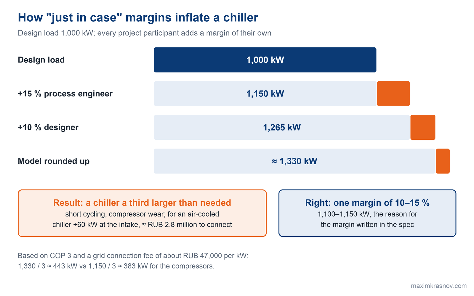
Chiller capacity for water is calculated with the formula Q = 1.163 × G × Δt: the flow rate in m³/h multiplied by the temperature difference and by 1.163. A flow of 20 m³/h cooled from 17 to 12 °C gives 116 kW. A margin of 10–15% is added to the result once. If every participant in the project adds a margin of their own, the chiller ends up a third larger than needed.
A wrong capacity figure is the first of the 13 mistakes I went through in my webinar on choosing a chiller in February 2026, and the most dangerous one. An undersized unit runs nonstop and never reaches the setpoint. An oversized one starts too often, and many modern chillers have a limit, for example no more than two starts per hour; start it more often and the unit trips on an alarm.
Below is how to get the capacity figure and which decisions on it belong to the owner, not the contractor. How to choose the type of chiller is covered in How to Choose an Industrial Chiller: 13 Most Expensive Mistakes; the rest is in the Chillers section.
How do you calculate chiller capacity from water flow and temperature?
Chiller cooling capacity (how much heat the unit removes from the water per unit of time) is calculated from flow and temperature difference: Q = G · c · ρ · Δt / 3600, where G is the flow rate, m³/h; c is the specific heat, 4.19 kJ/(kg·K) for water; ρ is the density, about 1,000 kg/m³; Δt is the difference between inlet and outlet temperatures, K. For water the formula reduces to Q = 1.163 · G · Δt, kW.
Example: a flow of 20 m³/h, water cooled from 17 to 12 °C. Q = 1.163 · 20 · 5 = 116 kW. You need a chiller of at least 116 kW under these conditions, and the caveat about conditions matters more than the formula itself; it is the subject of the next section.
Run backwards, the formula gives the flow rate: G = Q / (1.163 · Δt), and the flow rate determines the pipes and pumps.
| Cooling, kW | Flow at Δt 5 K, m³/h | Flow at Δt 7 K, m³/h | Flow at Δt 10 K, m³/h |
|---|---|---|---|
| 250 | 43 | 31 | 21 |
| 500 | 86 | 61 | 43 |
| 1,000 | 172 | 123 | 86 |
| 2,000 | 344 | 246 | 172 |
A 7 K difference instead of 5 K cuts the flow by 28%: at 1,000 kW that means a DN150 pipe instead of DN200 and a pump one size smaller. But the consumers must hold the same temperature difference, otherwise the chillers run underloaded; details are in the article on chilled water plant design schemes.
How do you estimate the cooling load if the water flow is not known yet?
If there is no flow figure, the load is estimated from the rated heat output of the equipment (a rough guide is its power consumption) and multiplied by a diversity factor, usually 60–80% of the sum of the nameplate figures. The diversity factor is the share of equipment that actually runs at full power at the same moment.
The sum of nameplate figures without a diversity factor is a common reason for a chiller twice the size it should be.
One peak figure is not enough. Ask the process engineer and the client for:
1. the peak load of each consumer separately, not as one total;
2. the daily load profile on a hot day, a mid-season day and a winter day, including nights and weekends;
3. load surges: a furnace start-up, a press switching on — how many kilowatts and over what time;
4. the required temperature accuracy: at ±1–2 °C step control is enough; tighter than that needs a variable frequency drive on the compressor or pump.
First on our list of typical design mistakes is a load given as a single total, without a profile and without a minimum. The consequence is predictable: at night the chiller short-cycles (switches on and off too often), and a buffer tank appears after commissioning, at extra cost.
Why does actual chiller capacity differ from the catalog rating?
The catalog gives capacity under standard conditions, usually water at 12/7 °C and outdoor air at 35 °C. Hotter air, colder water, glycol instead of water — and you get less cooling. That is why a chiller is selected not by a catalog line but by the operating point on its performance curve, and the manufacturer does this from the questionnaire.
Three things pull actual capacity down the most:
1. Air temperature at the condenser. An air-cooled chiller in a pit or behind a high fence draws in its own hot exhaust air and trips on high pressure in hot weather.
2. Glycol. A glycol solution has lower specific heat and poorer heat transfer: according to chiller manufacturers' data, at 7 °C leaving water a unit on 40% propylene glycol delivers 0.90 of its capacity on water, and on 30% ethylene glycol, 0.96. Write the glycol type and concentration into the questionnaire, otherwise the selection will be done for water.
3. Leaving water temperature. Below 5 °C at the evaporator outlet there is a high risk of freezing the heat exchanger, so glycol is needed, and with it the capacity correction from the previous point.
What safety margin should you add to chiller capacity?
A reasonable chiller capacity margin is 10–15%, added once and in one place. A justified margin covers specific causes: heat exchanger fouling over time, operation in extreme heat, piping losses, planned expansion.
The typical mistake is a margin at every step. The process engineer added 15%, the designer another 10%, the model was rounded up to the next size. The result is a chiller a third larger than needed that spends its whole life running in short cycles. Frequent starts wear out a compressor fastest of all: the starting current is many times the running current, and in the first seconds the oil has not yet spread.
Variable load is handled by capacity control steps and a buffer tank, not by a capacity margin.
How much does excess chiller capacity cost the owner?
Excess chiller capacity raises the electrical capacity at the service intake, which is paid for at grid connection, and shortens compressor life through frequent starts. The price of the chiller itself is not the main line here: a chiller with 20% more capacity usually costs not 20% but 5–7% more.
Let us work through the example from Fig. 1. The electrical load for the grid connection specification is calculated from the power of the chillers at the design point. For an air-cooled chiller with a coefficient of performance (COP, the ratio of cooling to electricity consumed) of 3, a 1,330 kW unit needs about 443 kW for its compressors, and a 1,150 kW unit about 383 kW. The difference is 60 kW. At a grid connection fee of about RUB 47,000 per kilowatt, that is roughly RUB 2.8 million paid once, up front, for cooling the site does not need.
If there is little spare capacity at the intake, an excess margin can kill the whole project. Orders of magnitude per 1,000 kW of cooling:
| Chiller | COP | Compressor power per 1,000 kW of cooling |
|---|---|---|
| Air-cooled chiller | 3 | 333 kW |
| Water-cooled chiller | 5 | 200 kW |
| Centrifugal chiller with a cooling tower | 6 | 167 kW |
With a permitted capacity of 250 kW, a 1,000 kW water-cooled chiller barely fits, because the pumps and cooling tower fans are added to the compressors, and an air-cooled one does not fit at all. How to free up electrical capacity on cooling I covered in a separate article, "Not Enough Power at the Plant".
How do you check that a chiller will not short-cycle at low load?
A chiller is sized for the peak, but it runs at the peak only a handful of hours a year. According to the statistics behind the IPLV part-load metric of the AHRI 550/590 standard, a chiller spends 1% of its time at full load, 42% at 75%, 45% at half load and 12% at a quarter. So after the peak is calculated, the minimum must be checked.
The check is simple: the site's minimum load must be greater than the minimum capacity step of one chiller. Example: a production building with a process load of 600 kW by day and 300 kW at night all year round, plus air conditioning of 400 kW in hot weather and zero in winter. The peak is 1,000 kW, the minimum is 300 kW on a winter night. Two 500 kW screw chillers with a minimum step of 25% can unload down to 125 kW. The minimum is 2.4 times the step, so one chiller unloads and runs without stopping.
If the process load dropped to 100 kW at night, the chiller would go into start-stop cycles. Then the design needs a buffer tank, a vessel that adds water volume to the loop so the compressor runs long, even cycles, or a smaller chiller. A guide for frequency: no more than six starts per hour and a cycle of at least 10 minutes; many chillers have an even stricter limit.
With short, predictable peaks the opposite technique works: thermal energy storage. The chiller is sized for the average load, charges the tank at night, and during the peak the consumer draws on the stored cooling. This makes the chiller 30–50% smaller.
How many chillers do you need, and how do you calculate N+1 redundancy?
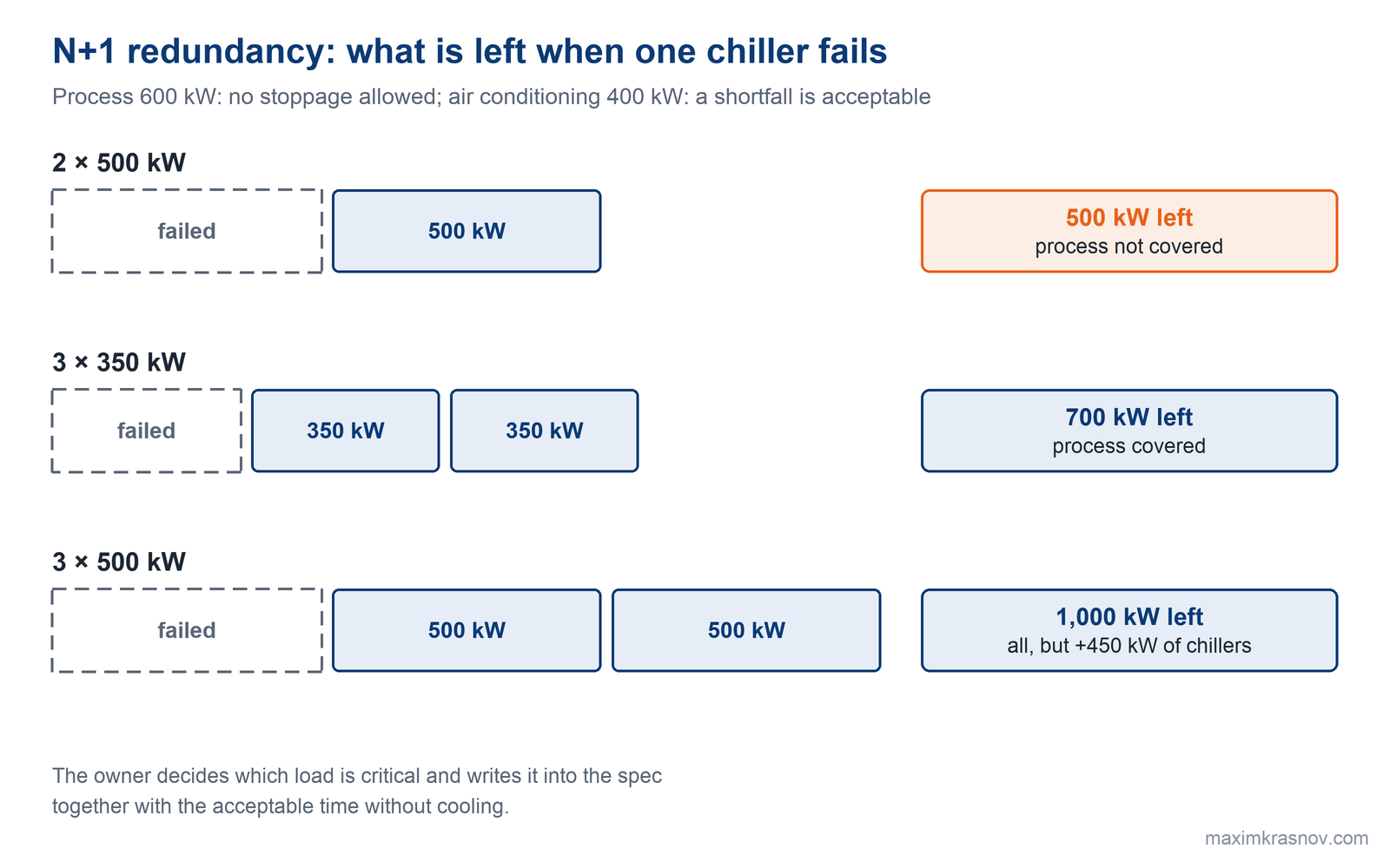
N+1 redundancy means that if any one chiller fails, the remaining ones cover the load the client has defined as critical. The key word is "critical": the decision on what exactly must keep running during a failure is made by the owner, not the designer.
Take the same building: a 600 kW process load that must never stop, and 400 kW of air conditioning where a short shortfall is acceptable.
| Option | Installed, kW | Left when one chiller fails, kW | What is covered after a failure |
|---|---|---|---|
| 2 × 500 | 1,000 | 500 | Process not covered: 500 is less than 600 |
| 3 × 350 | 1,050 | 700 | Process covered; in summer air conditioning is 300 kW short |
| 3 × 500 | 1,500 | 1,000 | Everything covered, full N+1 |
If only the process needs redundancy, three 350 kW chillers are enough: with one down, 700 kW remain against a need of 600 kW. Full redundancy for the whole peak takes three 500 kW chillers and 450 kW more installed capacity. Three 350 kW units have a second advantage: the smallest step at 25% is about 88 kW versus 125 kW, so a chiller handles the night minimum more easily and a smaller buffer tank is needed.
The client states the redundancy requirement in writing: the acceptable time without cooling, the chiller redundancy scheme, and redundancy of pumps and power supply. Chiller redundancy without power supply redundancy does not work.
How do you allow capacity for future production growth?
The growth margin goes not into the chiller but into the layout: space, pipes and valves for the next chillers. Some of our clients do exactly that: they order a design for three chillers and buy one for now. We draw all the pipes and valves, and the second and third chillers are installed later without a new design, without changing the piping or the pump group.
A chiller "to grow into" is also worth considering, since 20% more capacity costs 5–7% more, but then check the night minimum right away: otherwise it will short-cycle until the growth happens.
Key takeaways
1. Chiller capacity for water is calculated as Q = 1.163 · G · Δt: 20 m³/h at a 5 K difference is 116 kW under the given conditions.
2. Without a known flow, the load is taken from equipment nameplates with a diversity factor of 60–80%; the plain sum of nameplates gives a chiller twice the size needed.
3. A 10–15% margin is added once: three margins along the project give a chiller a third larger, and for an air-cooled chiller that means about 60 kW of excess capacity at the intake and around RUB 2.8 million for the grid connection.
4. After the peak, check the minimum: it must be greater than the minimum step of one chiller, otherwise you need a buffer tank or smaller chillers.
5. N+1 redundancy is calculated from the critical load, which the owner defines: for a building with a 600 kW process load, three 350 kW chillers do the job without an extra 450 kW.
FAQ
How do you calculate chiller capacity for cooling water?
Multiply the water flow in m³/h by the temperature difference in kelvin and by 1.163 to get the capacity in kilowatts. For 20 m³/h cooled from 17 to 12 °C that is 116 kW. Then add a single margin of 10–15%.
Why is a chiller with a large capacity margin a bad idea?
A unit much more powerful than the load reaches the setpoint quickly, stops and starts again. Frequent starts wear out a compressor fastest of all, and when the permitted number of starts is exceeded the chiller trips on an alarm.
How does catalog chiller capacity differ from actual capacity?
The catalog gives capacity under standard conditions, usually water at 12/7 °C and air at 35 °C. In hot weather, with colder water or on glycol the chiller delivers less: on 40% propylene glycol, for example, about 0.90 of its capacity on water. That is why a chiller is selected for the operating point of the site, not by a catalog line.
How much electricity does a 1,000 kW chiller use?
The order of magnitude is 167 to 333 kW for the compressors: about 333 kW for an air-cooled chiller with COP 3, 200 kW for a water-cooled one with COP 5 and 167 kW for a centrifugal chiller with a cooling tower at COP 6. Pumps and heat rejection fans come on top.
Sources
-
ANSI/AHRI Standard 550/590 "Performance Rating of Water-Chilling and Heat Pump Water-Heating Packages Using the Vapor Compression Cycle": IPLV part-load metric and operating mode weights.
-
ASHRAE Handbook — HVAC Systems and Equipment: design of chillers and chilled water systems.
-
SP 60.13330.2020 (Russian code for heating, ventilation and air conditioning).
-
Maxim Krasnov, webinar "13 Critical Mistakes in Choosing a Chiller", 26 February 2026.
-
Cold Energy (NCT) experience and calculations: engineering guide "NCT Chillers" (October 2026), NCT atlas "How to Choose a Chilled Water System" (August 2026), NCT chiller catalog 2026.
Need a cooling solution for your site? Get a consultation